 |
Ohio Automation, Inc. |
|
Mining Ventilation Software and More |
||
Engineering Software since 1985 |
||
| Home | AboutUs | MineSimU | MineVent | MineFire | MineWater | Downloads | ContactUs | Support | Services | Prices | Customers |
ICAMPS - Integrated Computer Aided Mine Planning Software |
|||||||
Call 740-596-1023 Today! |
|||||||
ICAMPS MineVent and MineVent 3D Mining Ventilation Software Analysis and Simulation |
|||||||
| The ICAMPS MineVent and MineVent 3D are mining ventilation software modules using expanded versions of the Hardy Cross Method for calculations. It also has a more robust second calculation engine called the Gradient Method. As-mined and projected timing maps serve as the basis for drawing to-scale mine ventilation schematic diagrams. Using AutoCAD snap features the planner designates nodes in the ventilation network. Except for the atmospheric nodes, each node must be assigned a unique number. The system prevents duplicate node numbers. The user connects the nodes with polylines which represent the actual branch airway path. The branch must have a start node and end node but you can have dummy nodes in between so that the actual branch path is used and the branch length can be calculated for use in the resistance formulas (see figure below). The branch length can also be typed in manually when calculating resistances. Each branch polyline has an associated attribute block that contains airway properties. Since the ventilation schematic is drawn to scale, the system can automatically compute the branch length and use the airway characteristics to calculate the branch resistance. The system has many features to simplify editing schematics and enhancing the ventilation diagram. All changes to a schematic drawing are stored permanently. |
|||||||
Special Features that may be unique to MineVent |
|||||||
|
|||||||
 |
|||||||
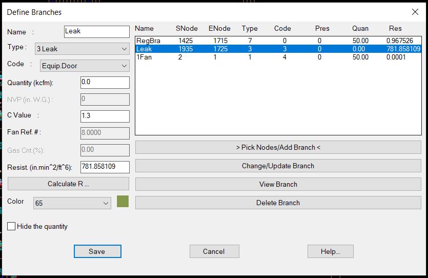
| Define Branches lets you easily select the nodes and all the branch/airway information with 7 different types (Normal, Fan, Leak, LimitQ, FixedQ, Dummy/Gas, and Regulator and 12 different codes. | |||||||
 |
|||||||
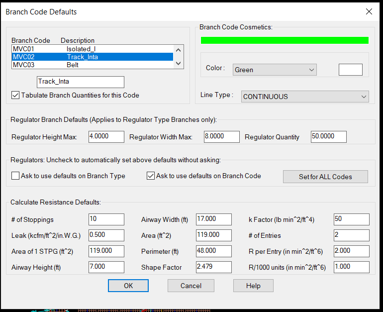
| The above is how you use the branch Code for cosmetic purposes and designate the layers (MVC01-MVC12). When defining or editing a branch you can assign or change the code which will affect the colors, layers, linetype and default resistance data for that branch. The nice thing is that you can just change the color, and linetype here and all the branches in the drawing will be updated. You can also use the AutoCAD layer command. | |||||||
 |
|||||||
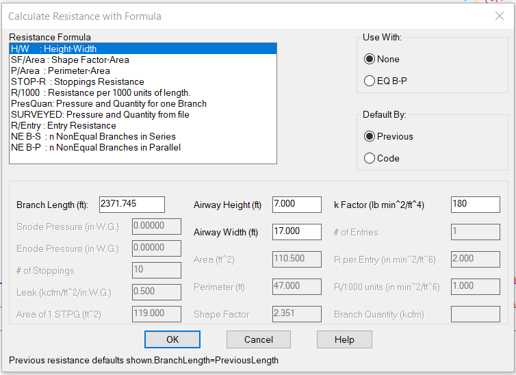
| Calculate the resistance dialog automatically calculates branch length.and lets you choose the formula that is right for you. Default numbers from Configure Branches if you click the Code radio button otherwise it defaults to the Previous values you entered. | |||||||
 |
|||||||
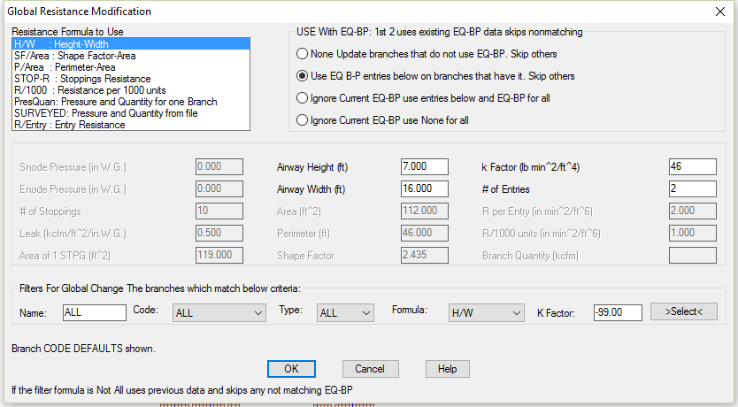
| The above shows a powerful way to change all or a group of branch resistances. You could also use the SURVEYED formula to change the resistances based on survey data from a file. | |||||||
 |
|||||||
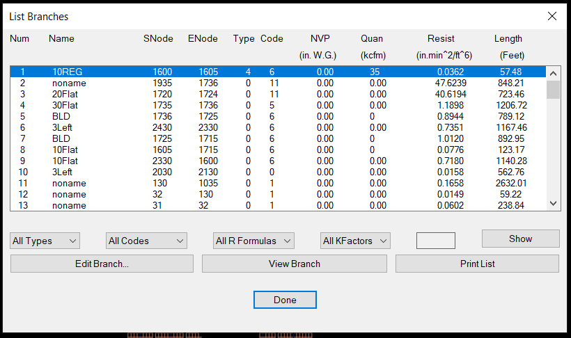
| The program has many helpful features for modifying the branches on the drawing or in List Branches where you can filter the branches you want to view and or edit. | |||||||
 |
|||||||
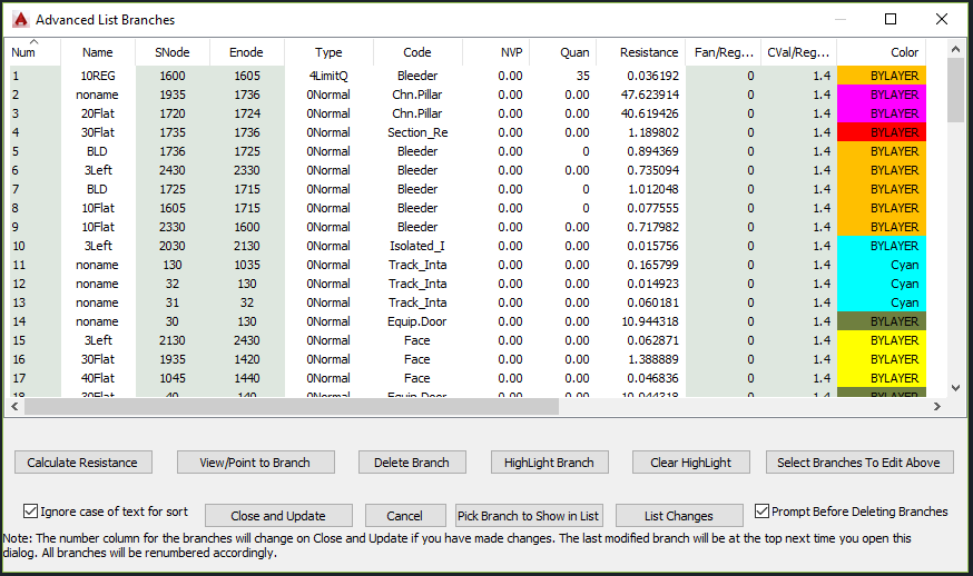
| Using Advanced List Branches you may sort by any parameter in the list ascending on first click the descending on the second. To sort by more than one sort by the Primary Last. | |||||||
 |
|||||||
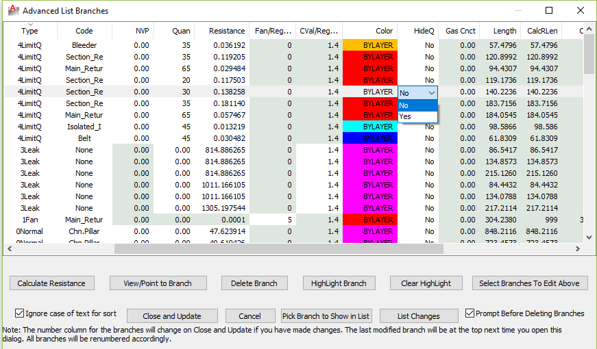
| The Advanced List Branches allows you to edit Branch information in form view with drop-down boxes and edit in place where appropriate. The lighter shade of green indicates values that cannot be changed in the list either because they are calculated or not valid for the branch Type. The above is sorted by branch Type descending. | |||||||
 |
|||||||
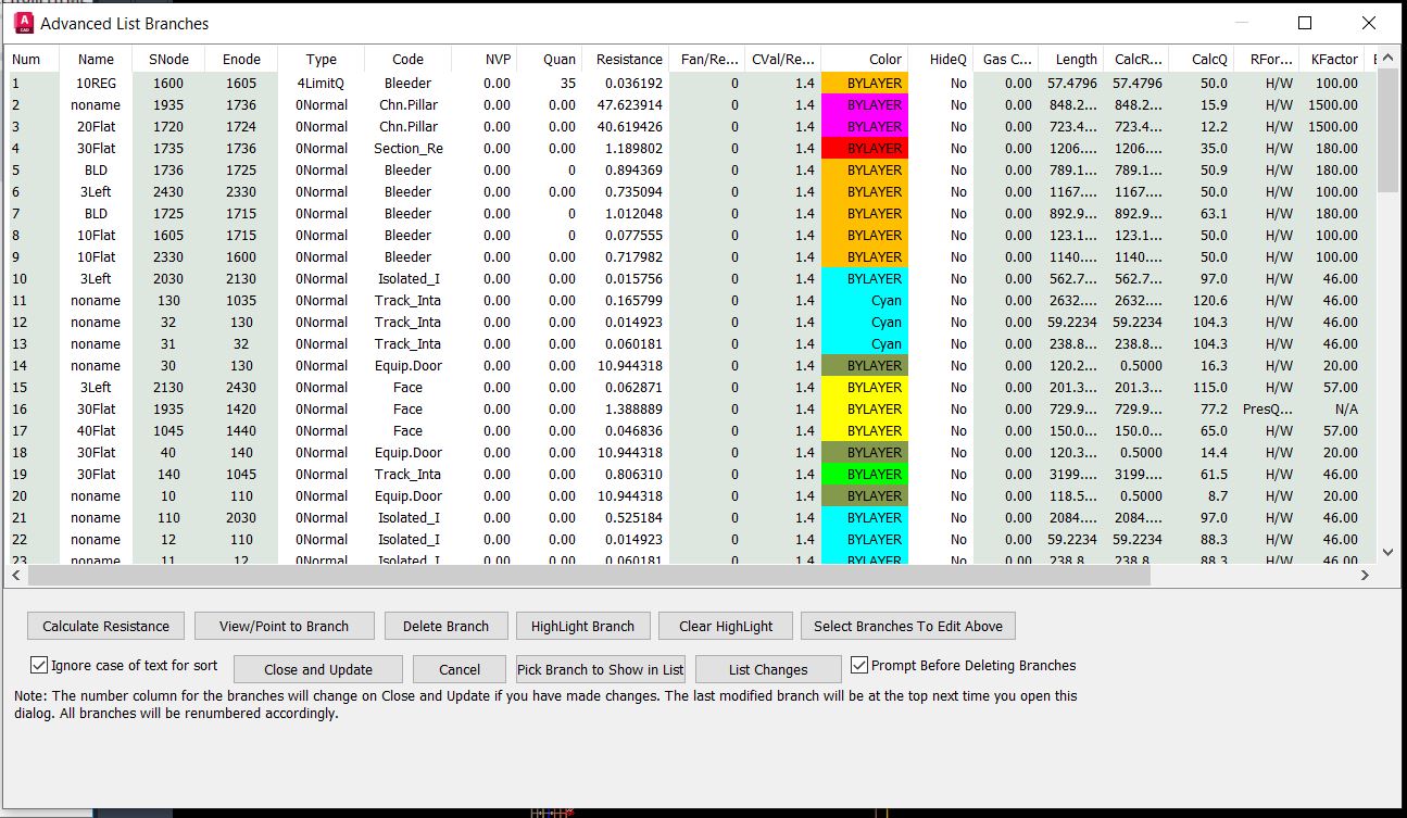
| The above shows the dialog resized to show all the useful information. | |||||||
 |
|||||||
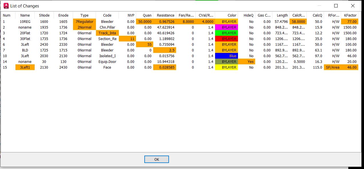
| The List Changes button on Advanced List Branches brings up the above dialog box that is sortable, resizable and shows the changes in Orange. | |||||||
 |
|||||||
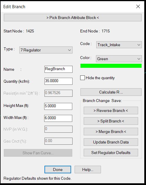
| The above shows how to edit or modify a single branch. This dialog can be activated by selecting a branch off the drawing or from most of the List Features. | |||||||
 |
|||||||
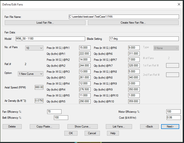
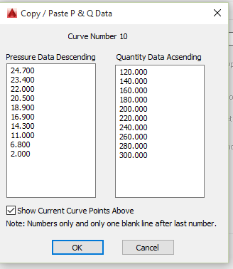
| The Define/Edit Fans allows you to move through the fan curves in a fan file and define new ones. You can choose a New Curve or a Modified Curve, which allows you to create an equivalent fan curve from 1 or 2 existing curves (UNEQ Series, UNEQ Parallel, EQ Series, EQ Parallel, or a Speed Density change). Other options are the Copy/Paste fan curve data, Show the Curve, List all the curves in the file and set the efficiency numbers for cost calculations. | |||||||
 |
 |
||||||
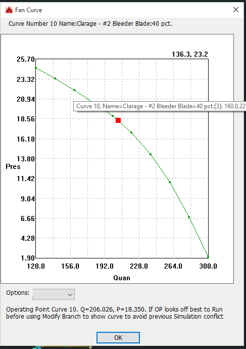
| You can show the fan curve graphically with the operating point in red as shown above. Hovering over a point shows information about the point and curve. There are options to show cross hairs, zoom in and zoom out and more. The top always shows shows the curve number, name and blade setting. | |||||||
 |
|||||||
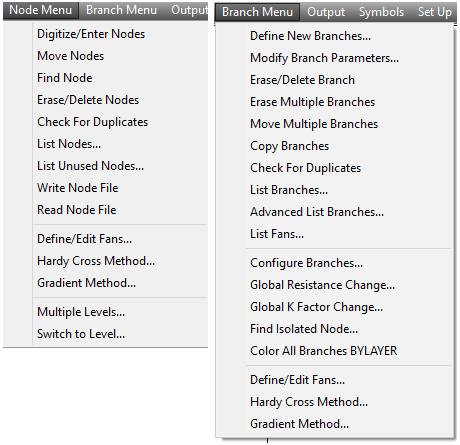
| Above are the main input menus for MineVent as well as the two different calculation engines Hardy Cross and Gradient. The Gradient has better convergence and is more efficient as far as how many iterations it takes to converge.The Hardy Cross is overall faster. It is useful to try both on the same model for various reasons. | |||||||
 |
 |
||||||
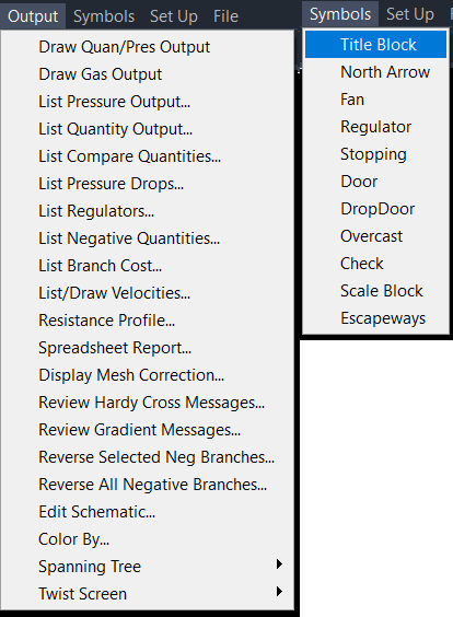
| Above are the main Output menus for MineVent. The most popular are Draw Quan/Pres Output, List Compare Quantities, List Negative Quantites, Edit Schematic and Color By. | |||||||
| Output consists of color coded schematics diagrams with branch quantities and node pressures displayed as shown below. The schematic can be plotted separately or superimposed on mine maps. The output also includes information for setting regulators. If the network analysis program (Hardy Cross or Gradient) yields unsatisfactory results or fails to converge, the system has numerous diagnostic features to help the user correct the schematic. The system has features that let the engineer highlight problem areas of the ventilation schematic based on the output. | |||||||
 |
|||||||
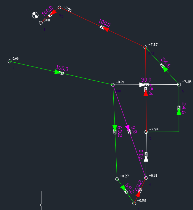
| The above is a sample of a Ventilation Schematic showing how it post the Airflow (kcfm in Magenta) on the airways and the pressures (in. w.g. White).on the nodes. If you are working in Imperial units, otherwise it is m^3/s and kPa. You can of course change the sizes on the numbers and the colors. The above is just a sample to show results and is not any kind of reasonable mine ventilation plan. | |||||||
 |
|||||||
 |
|||||||
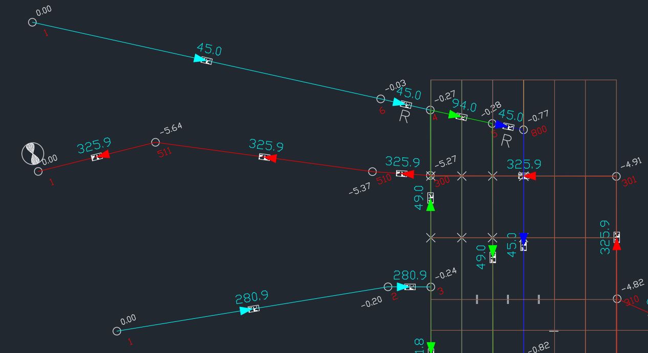
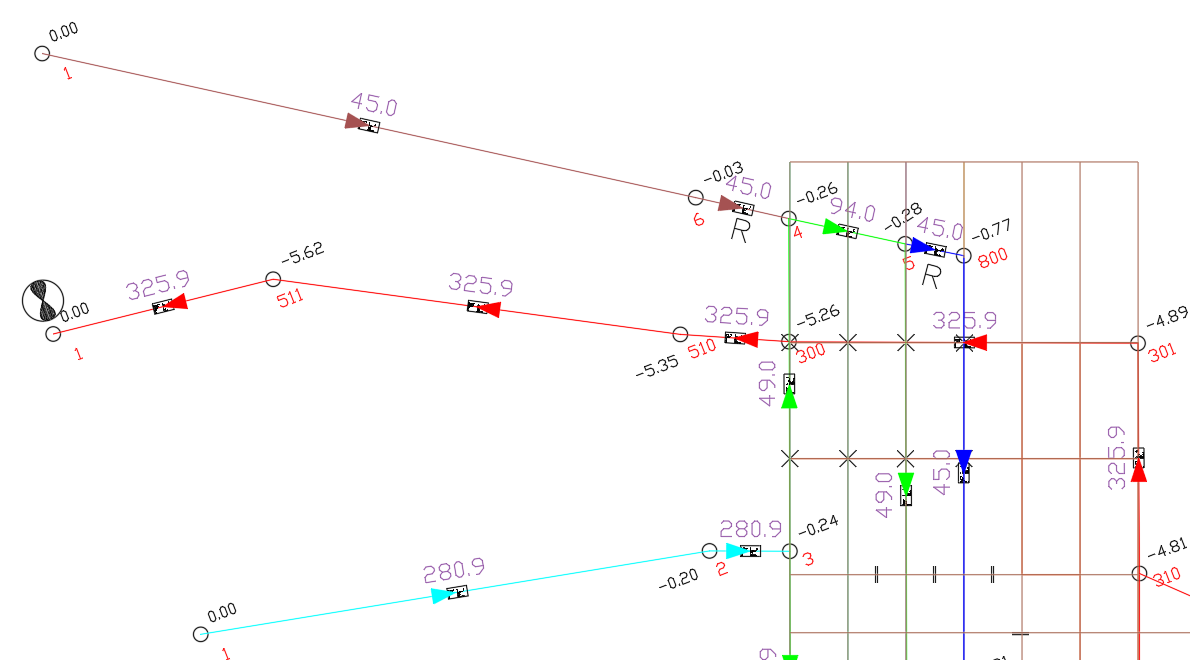
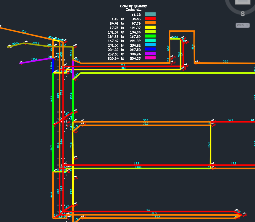
| Above is a section of a more realistic ventilation schematic showing how you can work off the mine map. Shows the kcfm on the branches and pressures and node numbers next to the node circles. You can notice how easy it is to change the colors of pressures and quanties by changing the layer color. | |||||||
 |
|||||||
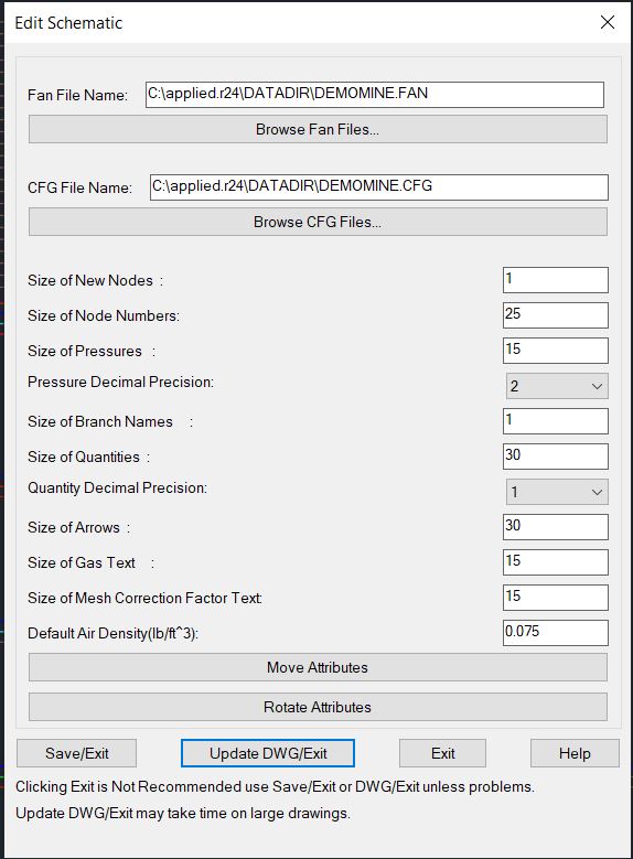
| You can change the sizes of text and arrows on the drawing and choose a decimal precision as well as Move and rotate parameters such as node numbers, pressures, quantities etc.. | |||||||
 |
|||||||
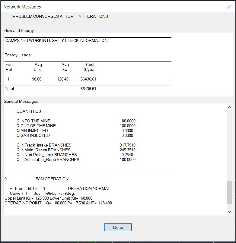
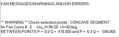
| The above shows the output of the Hardy Cross Method. There is more info if you scroll up. It can show you the fan operating point as well as whether any fan curves have concave or linear segments. | |||||||
 |
|||||||
 |
|||||||
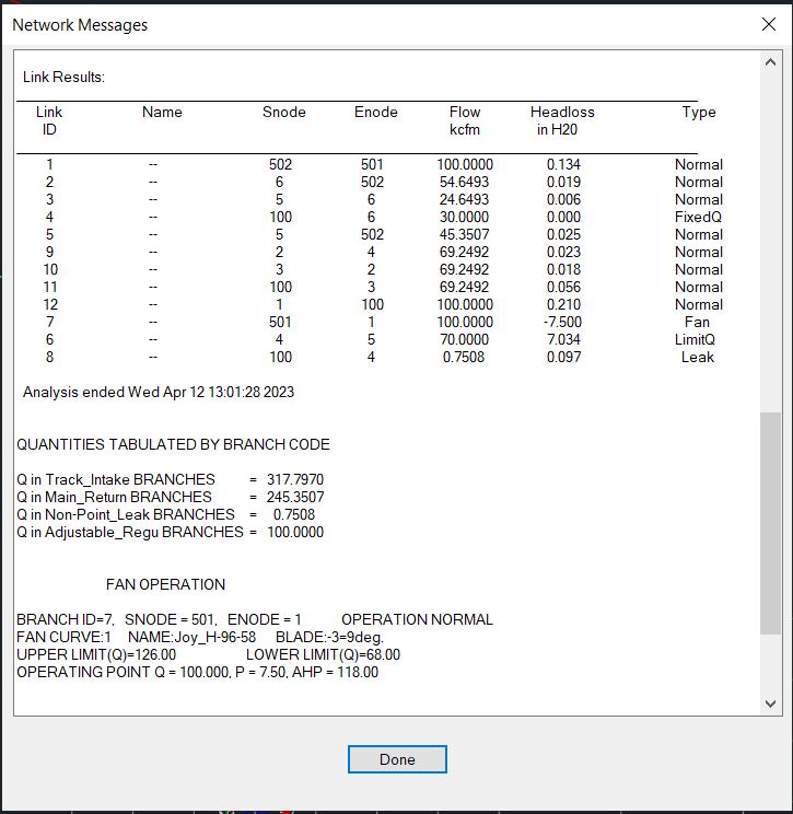
| The above shows the output of the Gradient Method. There is more info if you scroll up. It can show you the fan operating point as well as whether any fan curves have concave or linear segments. | |||||||
 |
|||||||
 |
|||||||
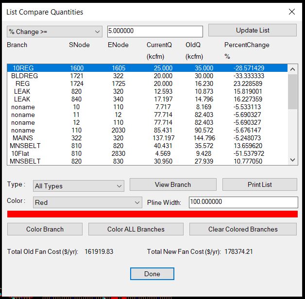
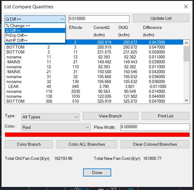
| The List Compare Quantities shows what happens on two consecutive runs if you change something. The above is the result in DemoMine.dwg by just changing 2 Limit Quantity branches. It also shows the difference in fan cost at the bottom for whatever change you made to the schematic. If you color it on the drawing selecting color Red you get the below. | |||||||
 |
|||||||
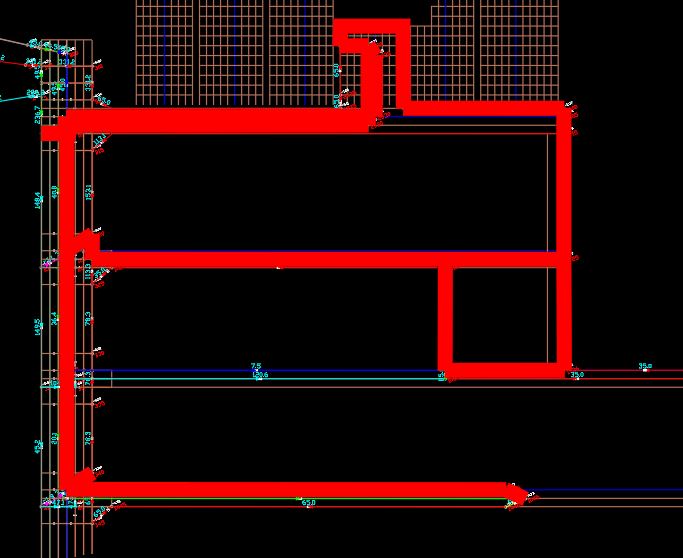
| The above was colored for a change of 5 percent and colored red the branches that changed by 5 percent or more with a line thickness of 100. | |||||||
 |
|||||||
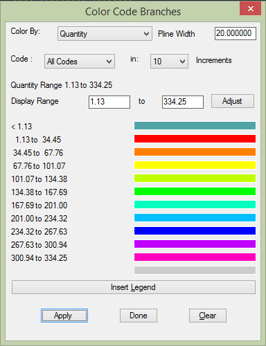
| The above shows the dialog interface for coloring by parameters Quantity, Air Horse Power, Gas, Resistance, Natural Ventilation Pressure, and Pressure Drop. | |||||||
 |
|||||||
 |
|||||||
 |
|||||||
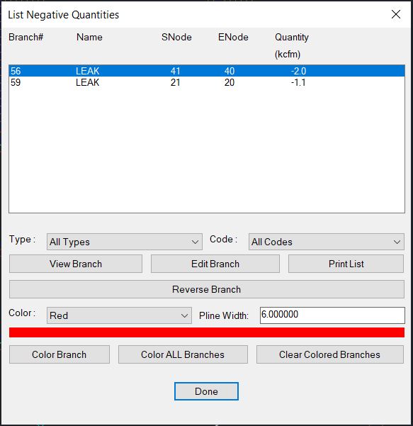
| The above allows you view and reverse any branches that have airflow going in the opposite direction as specified. There are also features to change them all at once or by drawing a polygon around the branches you want to reverse. | |||||||
 |
|||||||
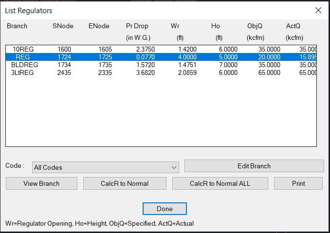
| The above shows you the regulator branches and the regulator opening, the desired quantity and the actual calculated quantity. | |||||||
 |
|||||||
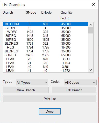
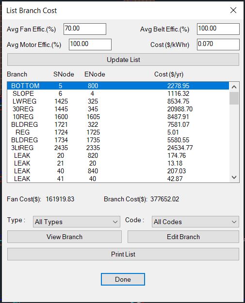
| The branch cost is calculated from the fan in use but you can change the numbers at the top and also choose only certain branch types or codes. | |||||||
 |
|||||||
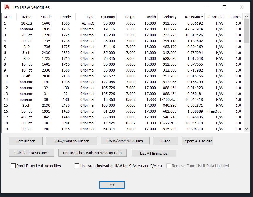
| List/Draw velocities lets you see all the velocity data and draw the velocity numbers on the opposite side of the quantity. This function is very powerful and can be useful even if you do not need the velocity data. The export function exports pretty mucn all data not just what is in the velocity list. It can be used as an alternative to List Branches and Advanced List Branches. | |||||||
| Main MineVent and MineVent 3D Mining Ventilation Software Features | |||||||
|
|||||||
© 2000 - 2007 Ohio Automation All Rights Reserved |